
Hydrodynamics Resistance Study for an 80–foot sailboat
Comparing SBS vessel x Long fixed modern bulb Keel
SBS's performance on vessels is very similar to the running of airplane wings in mid-flight. Through their wings configuration both systems allow the creation of a phenomenon known as lift.
Lift is a force resulting from the passage of a fluid through a specific profile. In this passage there is a variation of pressure as a function of velocity, geometry of the profile and its angle of attack in relation to the flow line. This lift has an action perpendicular to the wing´s chord, acting in the opposite direction to the boat´s weight. This lift reduces the vessel´s draft and consequently water friction resistance, thus generating better performance.
The effects of the use of SBS on the vessel hydrodynamic resistance were studied as a function of an 80-foot sailboat model, specially designed for this analysis. This hull was design having modern lines, aiming the best hydrodynamic performance.
The following figure shows the Body Plane generated by the FreeShip software.
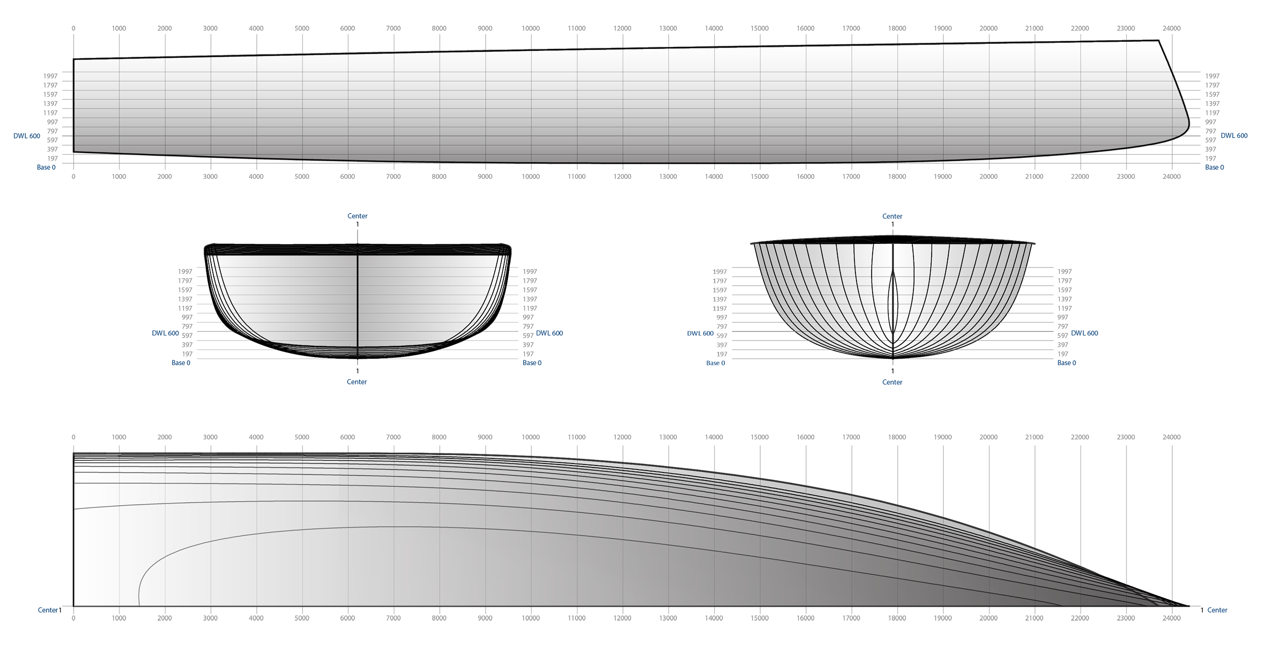
Figure 1: Body Plane for both Sailboats
From this hull two boat configurations were designed:
- The first boat having a conventional modern bulb keel of 3.34 m height and approximately 13 tons of ballast in the form of bulb;
- The second boat configuration having an SBS installed which allows reduction in keel dimensions. For this configuration the keel is 1.89 meters high and approximately 6.5 tons of ballast;
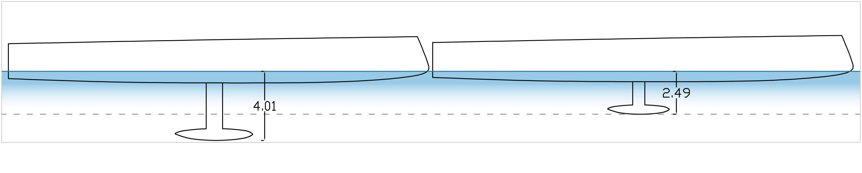
Figure 2: Different keels on the same hull
The configuration with SBS and smaller keel allows a reduction of 1.52 meters of draft, due to the smaller displacement of the boat.
Table 1: Comparison between hulls
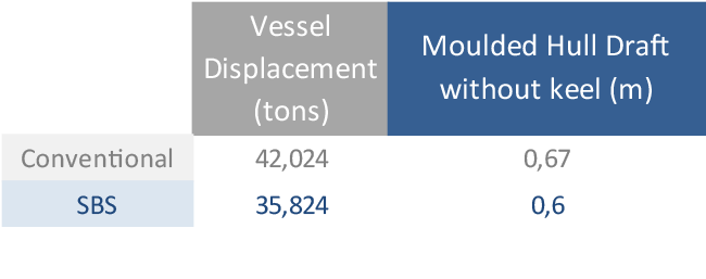
It is important to realize that the smaller displacement of the boat with SBS results in a lower draft also reducing the wave and the wet surface frictional resistance.
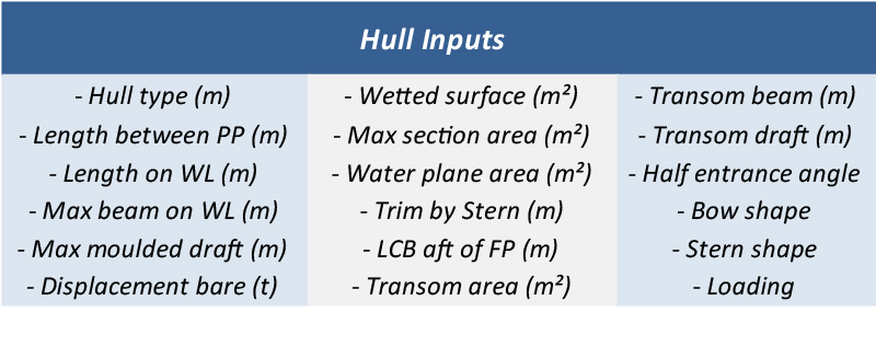
From the geometric vessel definitions and the determination of weights and centers, the necessary data for hydrodynamic resistance calculations were obtained. All calculations were performed on the NavCad software. The Hull particulars inputs provide the EHP (Effective Horse Power) values. The software works in function of specific systematic series, being used according to established parameters. These parameters consider several factors and proportions as shown in the table below:
Table 2: Calculation Input datas
After determining the design speeds and the hull "inputs" in the software, it is necessary to choose the systematic series that meets the vessel´s parameters values. It is important to emphasize that due to its differentiated character the analyzed hull could not be framed specifically in only one Series belonging to the software. Then, for greater accuracy with the values of the Series, the analysis were divided into 3 speed bands, the first one being from 2 to 10 knots, the second from 12 to 22 knots and finally the last one from 24 to 30 knots.
In the first range, a Basic Series of the program was used allowing estimates at low speeds.
Following, in the range from 12 to 22 knots, the Mercier Series was used. This Series is widely used in semi-displacement (semi planning) vessels.
Finally, in the range from 24 to 30 knots, the 1988 Jin method was used, which also has regression methods similar to systematic Series, such as NPL, NSMB, Series 63, etc ... These Series are related to planning vessels resistance.
In addition to the hull submerged characteristics, the software also considers the geometric characteristics above the waterline, taking into account the aerodynamic resistance to be overcome.
The keel and SBS in this first analysis had their hydrodynamic resistance calculated through the viscosity formulation suggested by Oossanen (1993).

The combined results for hull, keel and SBS were compared to similar vessels and proved to be reliable.
The following are the results of the EHP obtained for three conditions. The first is the conventional vessel, the second is the vessel with the SBS system not immerged but having the keel reduction of size and ballast. Finally the third is the vessel with the SBS in operation where the lift is generated by a wing immersed having an attack angle of 8 degrees. The lift varies according to the square of the speed, consequently there is a great boat displacement reduction in function of the increase of the speed. This reduction means that for each speed there is a different hydrodynamic resistance condition.
The wing that generates the lift along with the wing keel, which composes the SBS system, had their drag coefficients considered in all obtained EHP.
Graph 1: Hull Effective Horse Power
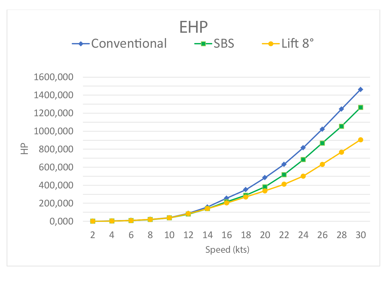
The graph above demonstrates a considerable reduction of EHP only by the reduction of ballast between conventional and SBS vessels, the gains are significant. It is possible to realize that for the same speed a much greater installed power is required in the conventional vessel.
In the range of 500 EHP, that shall correspond to an engine of approximately 800 BHP we are experiencing a difference of 4 knots. This easy calculation results in one hundred nautical miles more per a day trip.
Through the EHP for the different conditions it was possible to perform the speed boat simulation while sailing. (Sailors will love the new SBS reality)
The sail plan configuration was a sloop. The main sail was considered to have 180 m² and the genoa 162 m². The keel side area calculations were developed for the design speed of 12 knots as a function of the necessary side lifting force provided by the keel at a 5 degrees flow line angle of attack.
The keel area must be such that it supports the lateral force exerted by sails. If the keel does not provide the necessary support, there will be a leeway angle overloading the rudder, which will be required for heading compensation.
Here is another great advantage of the SBS. Due to its configuration the wing-keel is an asymmetric hydrodynamic profile and works together with the boat smaller bulb keel. It generates lift in the same direction of the keel lift force, allowing a much smaller keel. The SBS Wing Keel generates much more efficient lift than a symmetrical keel profile. In addition, the generated lift increases with the speed without needing angle of attack increase. More efficient sailing straight in line with the hull flow lines and appendages. No leeway angle.
The calculations were performed for real crosswind condition (90 degrees) with both sails, where it is expected to obtain a good simulation and comparison. For the vessel without SBS a leeway angle of 5 degrees was estimated, which is usually found in sail situations. For the vessel with SBS the angle was considered to be never more than 1 degree.
According to the calculation methodology provided by Oossanen (1993) and Larsson (1994) for the prediction performance, several factors must be considered; among them are the lift, drag and parasitic drag coefficients generated by the sails, in addition to the coefficient of drag due to the hull's sail area.
The following are the results that simulate the speed performance of the two boats while sailing. The comparison is made between the conventional vessel and the vessel with SBS system using angle attack of 8 degrees in the lift wing.
Graph 2: Comparison between powers generated by wind in the different boats
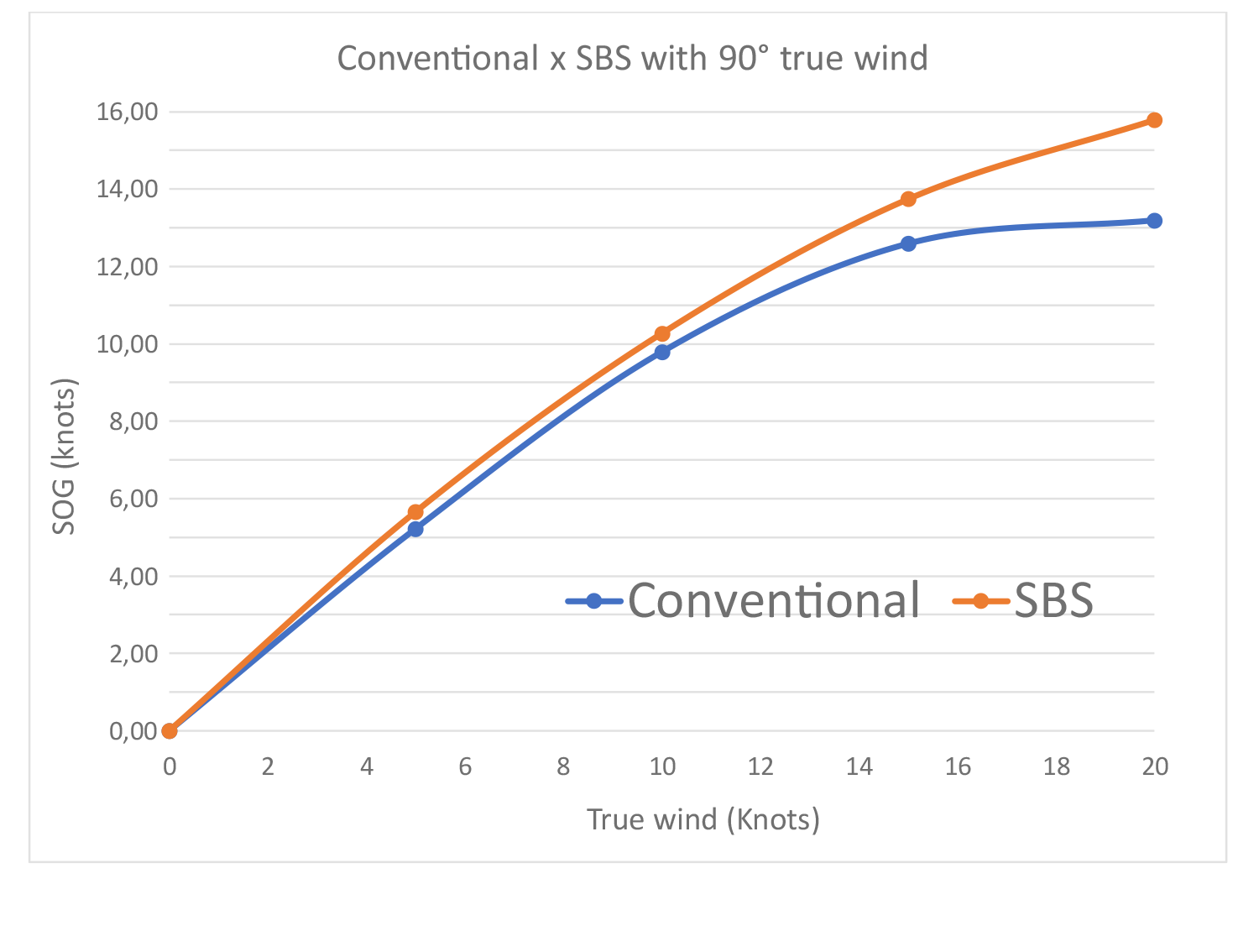
The results demonstrate the greater efficiency of the vessel with SBS at all wind speeds. This is mainly due to the reduction of wet surface, in addition to reducing the keel area causing a much smaller drag. From the graph above it can be observed that the difference between the boats increases as a function of speed, where from the 10 true wind knots the performance improvement is clear.
Another important point is that in the above graph the SBS set is immersed in the water from the minimum, almost calm, wind conditions. By experimenting with our prototypes having SBS installed, up to 10 knots of true wind and low hull speed, when SBS LIFT is still not as important, SBS wings can be kept out of the water. The weight of the boat greatly reduced by a much smaller keel and bulb, the smaller wet surface of the keel, the smaller wet surface of hull, all added up, make the boat with SBS unbeatable. In an hour of sailing with true winds of 5 to 8 knots, the boat with SBS opens an advantage of more than a mile over the conventional.
There are still other factors that were not considered in this study, all of which consistently still on favor of the SBS vessel:
1) The possibility of keeping the SBS wings not submerged in weak winds maximizing performance as mentioned above.
2) The absence of leeway maintains the rudder always in centered. The boat does not try to cross and sail against wind all time.
3) The choice of the most suitable heeling angle to be maintained in order that windward rudder is always kept out of the water reducing wet friction / wave / drag resistance.
4) The hull in the SBS vessel is always fully aligned with the water line flows due to the fact that the SBS Wing Keel generates huge lift without needing a leeway angle. (Asymmetric hydrodynamic profile shape)
5) The sail area plan is not reduced or distorted when the wind blows stronger due to fact that the captain choses the boat inclination. Is the captain option to riff sails, place SBS in automatic or increase manually the Lift Wing attack angle.
6) Is the difficult to measure the influence of SBS in making the boat planning at high speeds. For sure we know how fast a boat can speedway when foils lift the boat from the water. SBS system is installed forward from the center of gravity in order to lift the vessel but keep the rudder and transom in contact to the water avoiding too complicated controls and cruising instability.
In addition, the SBS reduces the discomfort of sailing with large angles of inclination, reduces side and pitching acceleration, maximizes all conditions while browsing engines, reduces draft while approaching marinas or coves, reduces sea rolling while anchored, reduces water boarding in the bow… etc…
Although this study does not consider all these factors, that together deeply contribute to a greater efficiency and speed of the boat, the results can be considered extremely satisfactory and representative, providing an idea of the improvement of the performance with the use of SBS.
In a very conservative way, not taking into account all factors not measured here, in a real wind of 11 knots SBS vessel would have a gain of more than 0.80 nautical miles for each hour of navigation (a mile and a half away) and with a real wind of 20 knots a gain of more than 2 nautical miles per hour of navigation (3.70 kilometers).
We are conducting studies using towing tanks running models of different sizes.
These Tank Tests follow the recommendations of the ITTC - International Towing Tank Conference and aim to evaluate and aggregate some of the advantages mentioned above that cannot be measured in a computer calculation.
We have no doubt that the nautical historians of the future will divide cruise and regatta sailing into two distinct eras.
Before and after the SBS system.
______________________________________________________________________
Bibliography
LARSSON, L., ELIASSON, R. E., 1994, Principles of Yacht Design. Camdem, Maine UK, International Marine.
OOSSANEN, P. V., 1993, "Predicting the Speed of Sailing Yachts" , SNAME Transactions, v. 101, pp. 337 - 397.
CONTACT
sbs@sbssystem.com.br
COPYRIGHT ® 2017 - ALL RIGHTS RESERVED