
Stability Study for an 80-foot sailboat
Comparing SBS vessel x Top quality fixed Keel 80-foot sailboat
This present work aims to analyze, quantify and compare the stability characteristics of two sailboats having 80-foot length over all and fixed keels. One vessel having an SBS system installed plus a short light keel and another having a long fixed heavy bulb keel without SBS.
The first step was to develop a sailboat hull based on similar vessels. The main features in these vessels was focused on a comfortable cruise sailboat, but also having exceptional performance under sail.
Regarding the comfort parameter the vessel should have an intelligent internal and external layout, as well as smoothness navigation with good stability.
In general, cruising sailboats are intended to prioritize good conditions of stability up to 10 ° inclination, since it will be in this band that the sailboat will spend most of it´s time while sailing .
Greater heeling angles require more willing crew, deeply reduces comfort at sea and furniture / objects must be kept locked in order to avoid movements during sailing trips.
Others literatures that are available in the Internet show the gains regarding speed and performance comparing SBS and top quality available sailboats.
As mentioned above, the objective of this work was to evaluate only stability criteria. Due to this fact, we did not prioritized other stages of the design spiral. However, when using similar vessels, one can understand that the analyzed parameters are within reliable project references.
After researching different top quality current sailboats from different shipyards, the preliminary dimensions obtained with similar vessels were used to make two hulls in 3D modeling software.
- For the conventional model, according to similar vessels, a bulb fixed keel ballast of 13.5 t and a loaded displacement of 42 tons was adopted while the total ballast weight corresponds to approximately 32% of the vessel displacement. For this ballast, a keel was developed having a 0.90 meters chord. The keel height was kept at 3,34 m, resulting a loading draft condition of 4,01 meters;
- For the SBS model, half of the previous vessel ballast applied (6.75 tons.), resulting in a keel height of 1.89 m and 0.70 meters chord, having a 35.82 tons displacement and a draft of 2.49 m. The ballast weight for this condition corresponds to approximately 19% of the total displacement. The draft was reduced by approximately 40% due to the decrease in ballast and the use of SBS.
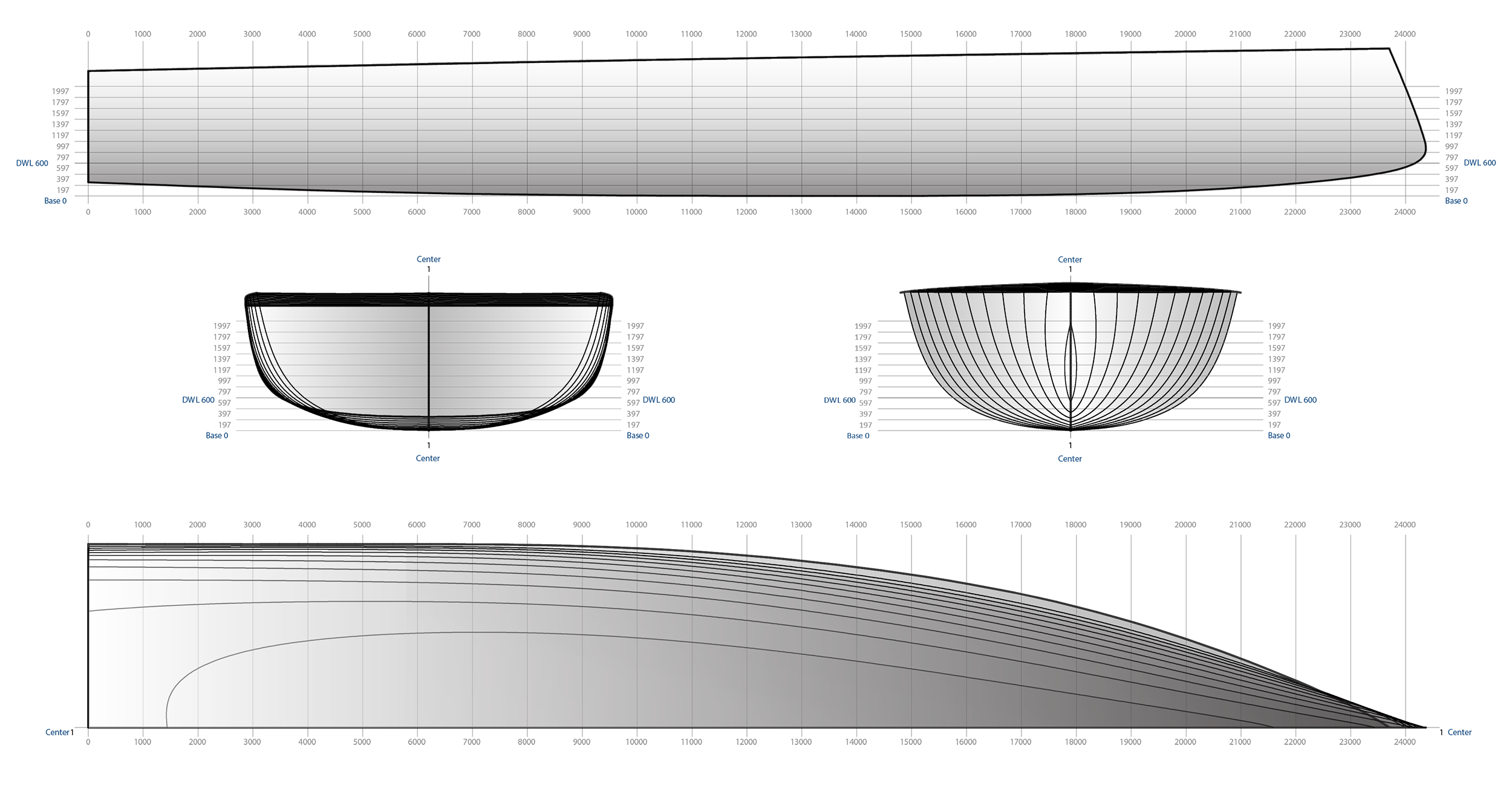
The following figure shows the Body Plane generated by the FreeShip software.
Figure 1: Body Plane for both Sailboats
After the hull definition, the two vessels weights and center of gravity were positioned and calculated. This work was performed in order to analyze both vessels initial stability. Once again, similar vessels were used to estimate the weights. Their distributions were made in order to minimize possible trim angles and initial lists.
Table 1: Weights and gravity centers for sailboat without SBS
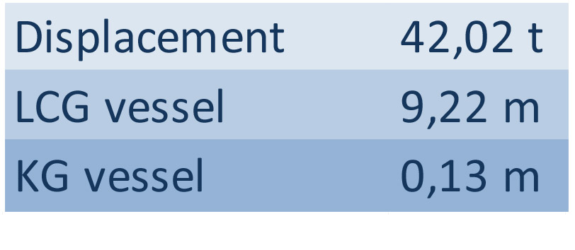
* Base line used as reference for KG, without considering keel.
Table 2: Weights and gravity centers for sailboat with SBS installed
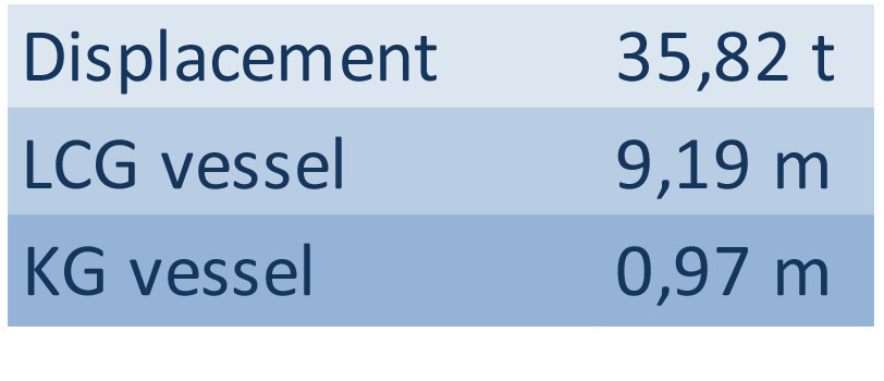
* Base line used as reference for KG, without considering keel.
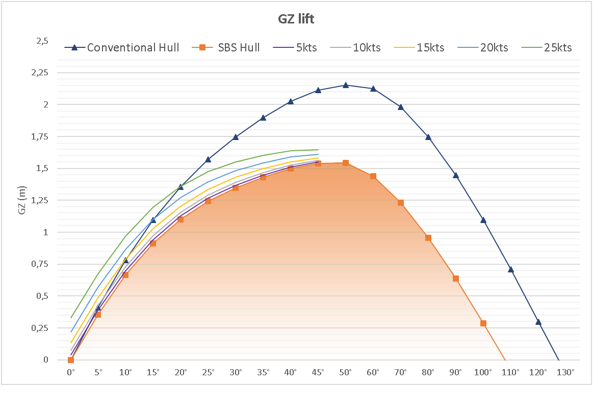
Static stability curves were then constructed. These curves were drawn in order to quantify which will be the vessel righting arm according to a certain heeling angle. This arm is known as GZ, the higher this value, higher will be the vessel's capability to return to its original stability condition. This value is directly related to the vessel weight distribution and hydrostatic hull parameters.
In the graphic below it can be seen that the conventional vessel has a higher initial stability, reaching a GZ maximum value of 2.15 m at 50 ° heeling angle. The SBS vessel at same condition has a 1.54 m GZ at 50 °. This value does not consider the vessel under motion and SBS action.
Graphic 1: Righting arm
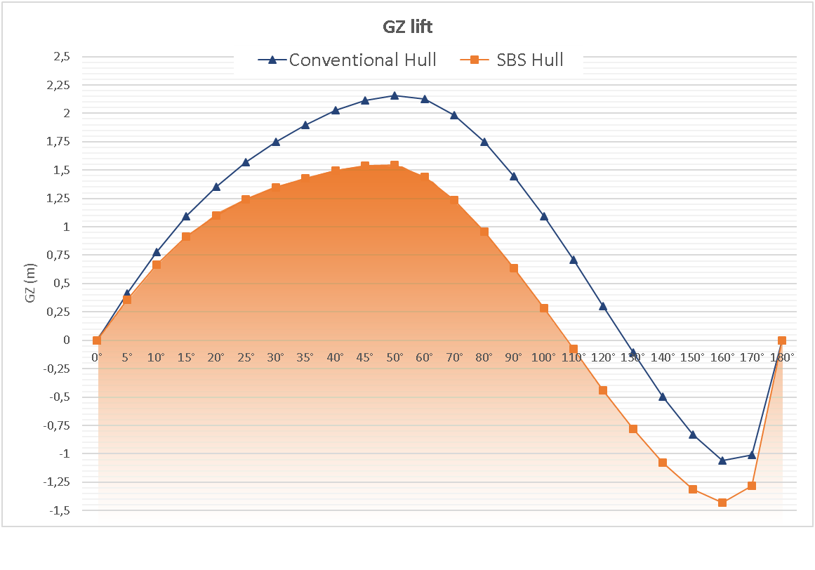
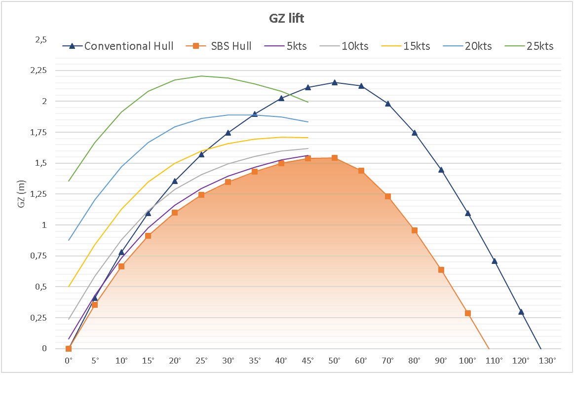
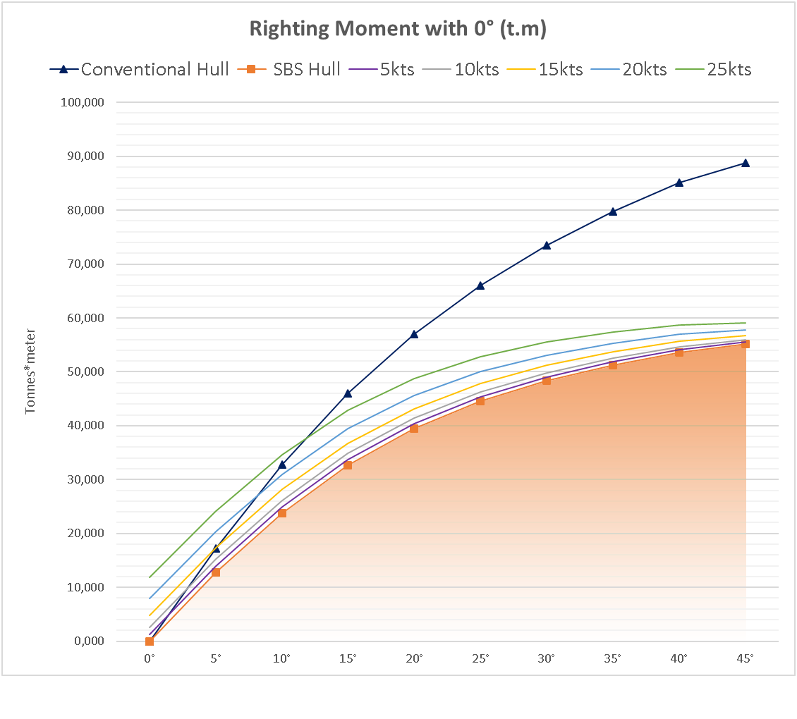
This difference was already expected due to the decrease in ballast of the vessel having installed the SBS system. The vessel with SBS has its center of gravity positioned approximately 0,84 m higher than that of the conventional vessel. It is important to clear out that the SBS lift wings used in these studies was designed having a span of 3 meters and 0.50 meters chord. The following graphic shows the GZ of the vessels, but now with the SBS results in operation.
Graphic 2: Righting arm plus lift SBS zero degrees lift wing angle
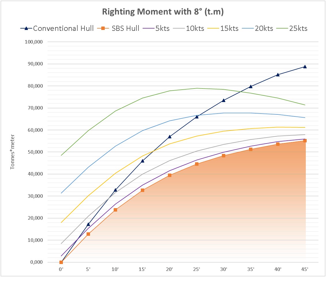
As the operating principle of the SBS is by lift generation, we have that the higher the lift better it's the performance. Lift increase occurs with the boat speed increase and/or with the increase of the lift wing angle of attack. The maximum attack angle for the lift wing adopted for this study was 8 degrees. The above graphic was drawn for 0 (zero) degrees of attack.
Graphic 3: Righting hull arm plus 8 degrees lift wing attack angle
The results obtained have great significance. The lift wing attack angle is just 8 degrees while the wing stoll angle is more than 15 degrees. A slight change in the lift wing attack angle creates an expressive transversal stability gain, surpassing the values obtained in the conventional vessel. It can be observed that in the speed of 5 knots up to 10° heeling, GZ values were obtained very close to that of the conventional vessel. Considering that a comfortable navigation generally does not surpass the 10° inclination, we can realize that the SBS brought great benefits to the boat stability. Finally we maximize the vessel efficiency having a much lighter displacement vessel with higher GZ from 0 to 10 degrees in any speed above 5 knots.
Table 3: Comparison of GZ gains with SBS

Stability gains can be much more significant if we raise further the lift wing attack angle.
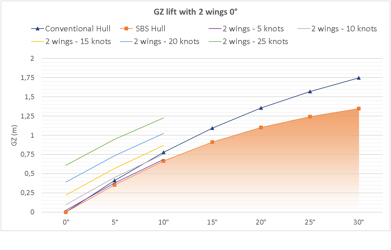
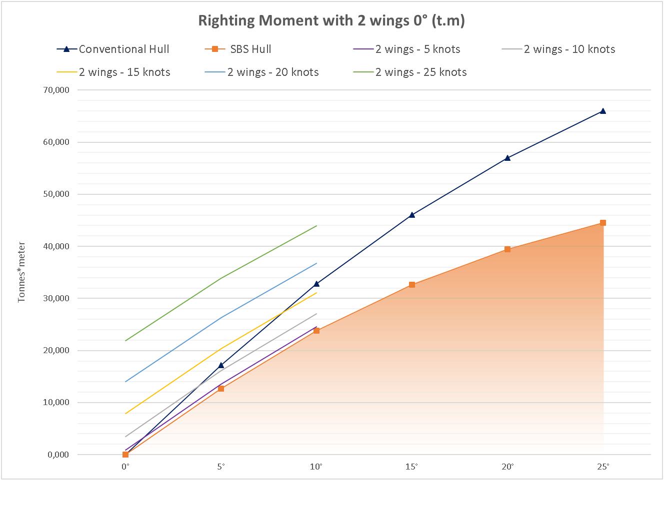
Another situation that will be analyzed in the next graph shows the possibility of using the two sides SBS wings at the same time immersed in the water (Port and Starboard). This configuration is only recommended for low angles of inclination, because with greater angles runs the risk of the windward wing being above the water line generating excessive drag and cavitation. The correct angle for using this configuration must be given according to the specific SBS design. For this case the maximum angle of 10° was considered. The following graph shows the comparison and the righting arm gain with the two wings immersed in the water, for a lift wing attack angle of 0°.
Graphic 4: Hull plus SBS GZ for 2 lift wings close to 0° attack angle
The following graph shows the same comparison, but having 8 ° lift wing attack angle.
Graphic 5: Hull plus SBS GZ for 2 lift wings 8° attack angle
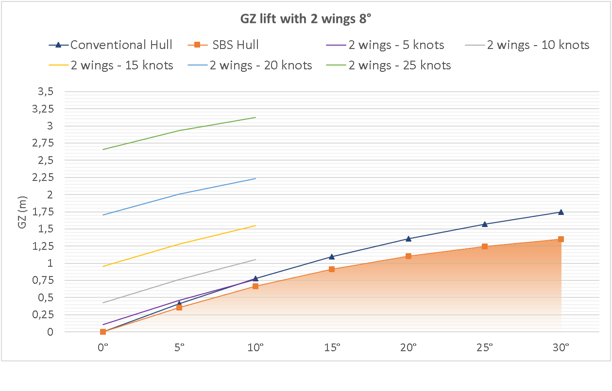
This configuration brings significant stability gains for the vessel as seen in the following table:
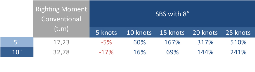
Table 4: Comparison of SBS gains with 2 wings and 8°

It is interesting to note that in a non-inclined navigation the initial stability of the vessel is significantly improved, in other words for the vessel to start turning it will require a much greater force.
In another words SBS sailboats will be able to sail up right, maximizing sail plan area and comfort at sea.
Our tank tests shown that SBS sailboats are faster than regular sailboats having both (port and starboard) in the water. The GZ at 10 knots at 5 degrees heel angle is almost twice the normal standard sailboat GZ. Less weight, faster and having all the other benefits of the SBS system (low draft, zero speed stabilizer, less wetted surface, less horse power needed while browsing engine, etc….). Another factor that must be analyzed comparatively for stability is the righting moment, that is the bending moment applied to return the vessel to it´s original equilibrium state. For these calculations the product of the vessel's righting arms (GZ) was made by its displacement, added to the moment generated by the SBS at each speed. The following are the results for both vessels.
Graphic 6: Static vessels (0 Knots speed) Righting moments
 Righting momentss.png)
Due to the greater displacement and the greater righting arm the conventional vessel has greater righting moment. The comparison between the vessels already using SBS is shown below.
Graphic 7: Comparison of righting moment with SBS use
When the comparison is made with 8 ° lift wing attack angle we have the following results:
Graphic 8: Comparison of righting moments 8° attack angle
It can be seen that once again the SBS raises the values of its vessel in order to compete directly with a conventional vessel in the range of 5 to 10 degrees, with half its ballast and 40% less draft. In the next table the gains obtained at the righting moment are compared with only one SBS wing immersed having 8 ° attack angle.
Table 5: Comparison of righting moments with one wing and 8°
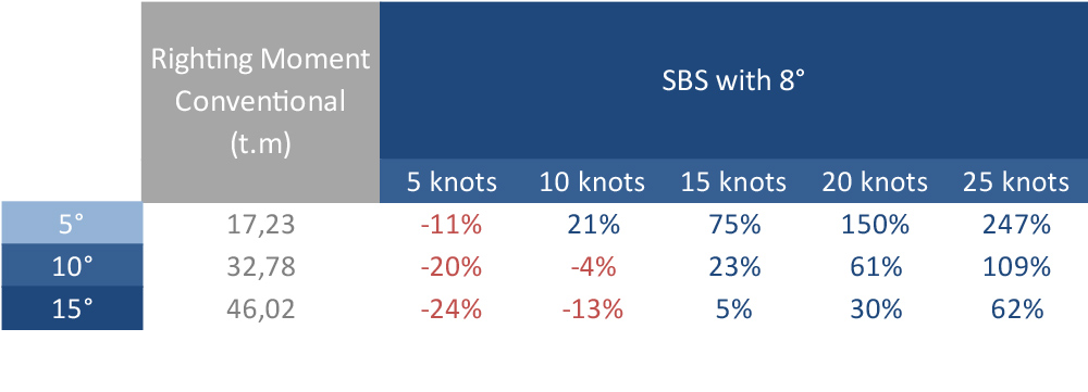
The righting moments obtained are showing that with only the leeward wing immersed having an attack angle of 8 ° higher efficiency was obtained at 10 knots. As the speed increases the SBS righting moment is amazing higher than the conventional sailboat.
The SBS has a lighter displacement and at speed it gets lighter again. All this with better stability and comfort.
When we analyze the configuration with the two wings (port and starboard) immersed, than we have the following results:
Graphic 9: Righting moment with 2 wings and 0° angle
If we consider the configuration with the same two wings immersed in an attack angle of 8 ° we will have the following results:
Graphic 10: Righting moment with 2 wings and 8° angle
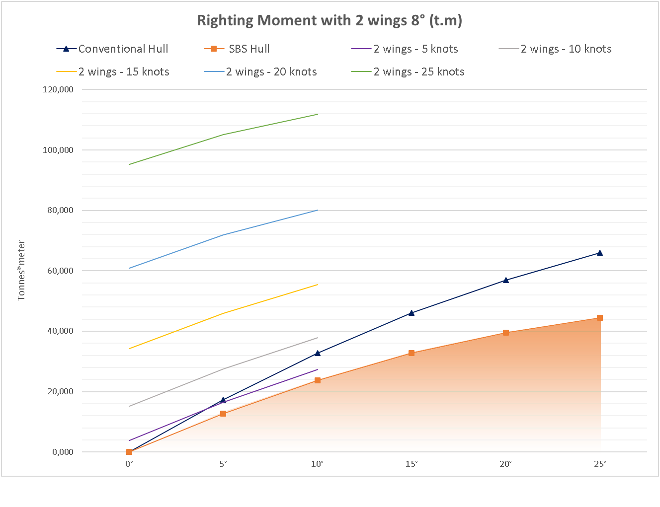
The comparison between the conventional vessel and the vessel with SBS in the configuration with the two wings in the water and angle of 8 °, can be seen as follows:
Table 6: Righting Moment Comparison
In view of the excellent transverse stability gains demonstrated in the above results it can be projected that this vessel will be able to ride always at high speeds and much safely.
To sail and cruise upright is now possible, comfortable and faster.
In view of the obtained results, it can be stated that SBS allowed a significant increase in the stability of the vessel, contributing to increase its GZ and its righting moment for different angles of trimming as well as for several speeds of operation. Another fact that should be emphasized is that this gain in stability was realized with a significant reduction in the ballast of the vessel as well as in its draft, making the vessel more efficient.
We would like to thank all support and dedication provided by towing tank teachers and interns of Jaú Technology College (FATEC), in special to MSc. Alex de Almeida Prado and MSc. Vladimir Cancian Junior that helped the SBS team to bring a new horizon and possibilities to the designers and sailors of the entire world.
CONTACT
sbs@sbssystem.com.br
COPYRIGHT ® 2017 - ALL RIGHTS RESERVED